
A 138 kV substation, unused.
Available now.
Power transformers and circuit breakers from a single cancelled capital project, engineered as one 138 kV set, factory new, never energized. Complete with certified factory test reports and released manufacturer drawings. Available as individual units or by the lot.
Disclosed up front: the transformers are DETC, not LTC. They suit designs where voltage regulation is handled elsewhere. At 137,920 lb each they are a permitted heavy-haul move.
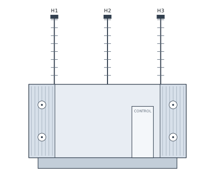
- Power transformers
- 7
- Aggregate, 7 × 50 MVA at 55°C
- 350 MVA
- New-build lead time at this class
- 40-70 wk
- These units
- On the ground
Power transformers
Seven 138 kV substation transformers, new and unused, never energized. 30 / 39.9 / 50 MVA ONAN/ONAF/ONAF at 55°C rise, 33.6 / 44.7 / 56 MVA at 65°C. HV 138,000 V delta, 650 kV BIL. LV 13,800Y / 7,967 V, 110 kV BIL. Three phase, 60 Hz, Dyn1, copper HV and LV windings, five-position DETC. Built February 2025 to IEEE C57.12.00, with a certified factory routine test report.
Impedance is quoted on both bases. A fault study run against the 56 MVA rating uses 17.29 %, not the 9.26 % figure carried on the 30 MVA base.
Ratings
| Rating | Value |
|---|---|
| Capacity, 55°C rise | 30 / 39.9 / 50 MVA |
| Capacity, 65°C rise | 33.6 / 44.7 / 56 MVA |
| Cooling | ONAN / ONAF / ONAF |
| Phase / frequency | 3 Ø · 60 Hz |
| HV winding | 138,000 V delta |
| LV winding | 13,800Y / 7,967 V |
| Rated current, HV / LV | 125.5 A / 1,255.1 A |
| Vector group | Dyn1 |
| BIL, HV / LV | 650 kV / 110 kV |
| Impedance, 30 MVA base | 9.26 % at rated tap |
| Impedance, 56 MVA base | 17.29 % at rated tap |
| Zero-sequence impedance | 10.30 % (0.65 Ω/phase) |
| Standard | IEEE C57.12.00 |
| Date of manufacture | February 2025 |
Tap changer
| Tap | HV volts | A @ 56 MVA | Link |
|---|---|---|---|
| A | 144,900 | 223.1 | 4-5 |
| B | 141,450 | 228.6 | 5-3 |
| C | 138,000 | 234.3 | 3-6 |
| D | 134,550 | 240.3 | 6-2 |
| E | 131,100 | 246.6 | 2-7 |
Five position, de-energized operation only.
Construction
| Item | Detail |
|---|---|
| Core | Stacked |
| Windings | Copper, HV and LV |
| Insulating fluid | Type II mineral oil, specified under 2 PPM PCB |
| Oil volume | 5,490 gal: 4,890 tank / 600 radiator |
| Cooling fans | 12 |
| Local control panel | NEMA 3R |
| Paint | ANSI 61 light gray |
| Protection and monitoring | Sudden pressure relay, pressure relief device, oil and winding temperature indicators, oil level indicator, N2 gas equipment |
| Tank | Welded, full vacuum and 14.7 psi internal |
Bushing CTs
| CT | Location | Ratio | Class |
|---|---|---|---|
| CT01-03 | H1, H2, H3 | 600:5 MR | C800 |
| CT04-06 | X1, X2, X3 | 2000:5 MR | C800 |
| CT07 | X2 (WTI) | 3500:5 SR | 3.2 CL |
| CT08 | X0 | 2000:5 MR | C800 |
Weights
| Item | Value |
|---|---|
| Core and coil | 67,615 lb |
| Tank and fittings | 30,460 lb |
| Insulating oil | 39,845 lb |
| Shipping weight | 84,100 lb |
| Total weight | 137,920 lb |
| Overall L × W × H | 205 × 196 × 201 in |
| Shipping L × W × H | 192 × 96 × 144.5 in |
Routine tests
| Routine test · documented unit | Guarantee | Measured |
|---|---|---|
| Turns ratio error across taps | ±0.5 % | 0.02-0.25 % |
| Polarity and phase relationship | Dyn1 | Dyn1 |
| Winding resistance @75°C, HV | — | 1.5172-1.5187 Ω |
| Winding resistance @75°C, LV | — | 0.01050-0.01054 Ω |
| Insulation resistance, HV-LV | — | 19,400 MΩ |
| Insulation resistance, HV-earth | — | 20,800 MΩ |
| Insulation resistance, LV-earth | — | 15,900 MΩ |
| Core-clamp insulation | — | 8,130 MΩ |
| Insulation power factor @20°C | 0.5 % | 0.19-0.22 % |
| No-load loss @100 % / @110 % | — | 22,601 / 27,459 W |
| Exciting current @100 % / @110 % | — | 0.16 % / 0.25 % |
| Efficiency @PF 1.0, 100 % / 50 % | — | 99.66 / 99.72 % |
| Applied voltage, HV-earth | 207 kV | Withstood |
| Applied voltage, LV and neutral-earth | 34 kV | Withstood |
| Induced overvoltage, LV Ø-Ø @180 Hz | 27.60 kV | Withstood |
| Oil leakage, +0.50 kgf/cm² × 12 h | — | Passed |
| Control cubicle dielectric and wiring | — | Passed |
| Operation test, all devices | — | Passed |
| Bushing CT ratio, polarity, IR | — | Passed, >100 MΩ |
| Sweep frequency response analysis | — | Recorded |
Performed on the documented unit, February 2025.
Losses by tap
| Losses and impedance | Tap A | Tap C | Tap E |
|---|---|---|---|
| Load loss @75°C, 30 MVA (W) | 76,326 | 77,896 | 80,957 |
| Total loss @75°C, 30 MVA (W) | 98,927 | 100,497 | 103,558 |
| Load loss @85°C, 56 MVA (W) | 270,714 | 276,387 | 287,130 |
| Total loss @85°C, 56 MVA (W) | 293,315 | 298,988 | 309,730 |
| Impedance @75°C, 30 MVA (%) | 9.22 | 9.26 | 9.42 |
| Impedance @85°C, 56 MVA (%) | 17.20 | 17.29 | 17.59 |
Type tests
| Type test · sister unit | Guarantee | Result |
|---|---|---|
| Lightning impulse, HV winding | 650 kV | Withstood |
| Chopped wave, HV winding | 715 kV | Withstood |
| Lightning impulse, LV and neutral | 110 kV | Withstood |
| Top oil temperature rise, ONAN | 55 K | 42.6 K |
| Avg winding rise, HV / LV | 55 K | 43.5 / 42.4 K |
| Hot-spot rise, HV / LV | — | 54.6 / 53.2 K |
| Sound level, no cooling | 75 dB | 71.5 dB |
Type tests were performed on a sister unit of the same design in December 2024, standard practice for a production run. Results are not attributed to an individual unit.
145 kV SF6 circuit breakers
Five SF6 dead tank circuit breakers, new and unused. 145 kV / 2000 A / 40 kA, 650 kV BIL, 60 Hz. Rated interrupting time 3.0 cycles. Spring mechanism with 125 VDC control and dual trip coils. Twelve 1200:5 multi-ratio C800 bushing CTs. IEEE 693 seismic qualified to 0.2 g RRS. US built, 5,555 lb each.
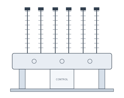
| Type | SF6 dead tank |
| Rated maximum voltage | 145 kV |
| Rated interrupting time | 3.0 cycles |
| Voltage range factor K | 1.0 |
| Short circuit, terminal fault | 40 kA |
| 90 % short line fault | 40 kA |
| Short circuit withstand | 3 s |
| DC component | 55.2 % |
| Continuous current | 2000 A |
| Frequency | 60 Hz |
| Full wave impulse withstand | 650 kV |
| Duty cycle | O-0.3s-CO-15s-CO |
| Out-of-phase switching | 10 kA |
| Temperature range | −30°C to +40°C |
| Capacitance switching, voltage factor | 1.4 |
| Line charging / isolated bank / back-to-back | 160 / 400 / 400 A |
| Inrush peak / frequency | 20 kA / 4,250 Hz |
| Mechanism | Spring |
| Closing coil | 125 VDC, 3.5 A |
| Trip coils | 125 VDC, 3.5 A each, dual |
| Spring charge motor | 125 VDC, 1.6 kW |
| Space heater | 120 VAC, 190 W |
| Bushing CTs | Twelve, 1200:5 MR, C800, RF 2.0 |
| BCT taps | 100:5 through 1200:5 |
| Bushings | Porcelain, ANSI 70 gray, 92 in creepage, 44.5 in strike |
| Control cabinet | NEMA 3R steel |
| SF6 pressure @20°C | 93 / 78 / 74 psig: normal / alarm / lockout |
| SF6 weight | 71 lb |
| Seismic | 0.2 g RRS per IEEE 693 |
| Weight, breaker / BCTs / gas | 3,744 / 1,740 / 71 lb |
| Total weight | 5,555 lb |
| Shipping L × W | 135.8 × 85.1 in |
| Origin | Designed and manufactured in the USA |
New, unused, never energized
Both lots, released from a cancelled capital project. On the transformers: factory paint intact with no field weathering, bushings not yet mounted with openings sealed and wrapped from the factory, stored outdoors on timber cribbing.
| Document | Status |
|---|---|
| Certified factory routine test report | Available now |
| Type test results, sister unit | Available now |
| Outline, nameplate and layout drawings | Available now |
| Instruction and maintenance manual | Available now |
| Breaker outline and schematic drawings | Available now |
| Oil test report and PCB certificate | In process |
| Manufacturer identity, serials, location | NDA / LOI |
| Shipping weight per unit | 84,100 lb |
| Total weight per unit | 137,920 lb |
| Shipping envelope | 192 × 96 × 144.5 in |
| Move classification | Permitted heavy haul |
| Rigging, permits, escorts | Buyer's account |
At 137,920 lb per unit this is a permitted heavy-haul move in every jurisdiction. Freight is the largest single variable in landed cost at this class. A route survey is recommended before an offer is firmed.
How a sale closes
Pricing is released by reply to a qualified request. Offers considered.
| Seller of record | Maverick Wholesale LLC |
| Pricing | USD, EXW storage location, released by reply |
| Freight, rigging, permits | Buyer's account unless quoted separately |
| Closing | Independent escrow: buyer funds escrow, title transfers and funds release at the same closing |
| Inspection | Available to a qualified buyer by appointment |
| Structure | Individual units or by the lot |
When do you need to energize?
Tell us about the 138 kV service and the date it has to be live. We reply with pricing, drawings and test reports.
Call or text · 689-666-0287Manufacturer identification, serial numbers, order and drawing numbers, unit tags and storage location are withheld at this stage. Brand and general location are released under executed NDA; serial numbers are released at LOI.
Pricing is offered subject to prior sale and to material remaining available at time of order. This document is an offering, not a binding commitment to sell.
Impedance, loss and dielectric values are transcribed from the certified factory routine test report; type test results are from a sister unit of the same design. Oil is specified under 2 PPM PCB per the released manufacturer drawing; oil analysis furnished on request. Material offered as-is, where-is with no warranty expressed or implied unless stated in a signed purchase agreement. Manufacturer warranty status has not been established. Buyer is responsible for verifying suitability for the intended application. Complete documentation furnished on execution of a confidentiality agreement.